Did you know, that there is an extra hole (unseen by most), where water easily can creep in? Do you want to see high-resolution photos of some improvements? Come and join me on my tour! :)
This is just a journey that I did, I don’t recommend anyone to do these modifications. You can lose your warranty or your life, so do it at your own risk.
Be wise, if something breaks under you while you are in traffic, that’s bad. By the way that’s why I don’t go into - heavy - traffic with my scooter, and why I’m avoiding the situation where I have a car behind me.
These machines are immature, with no regulations, no quality standards. They break everywhere all the time. But, if used carefully, they are a lot of fun. :)
Fixing the controller’s heat management
I’ve heard of many with the PRO version who have their controller burned down, especially when using KERS or under excessive load. It seems that the PRO has a similar controller (or it might even be the same - leave me a comment if you have information on this) than the non-PRO, but the motor’s rated power is higher.
Therefore many recommend adding extra thermal grease under the FETs.
Although mine is not a PRO, I’ve decided to play safe and did it on mine also.
Getting it apart
Before completely pulling every wire, I’ve made a photo of the motor’s main wires just to be sure about their order.
[
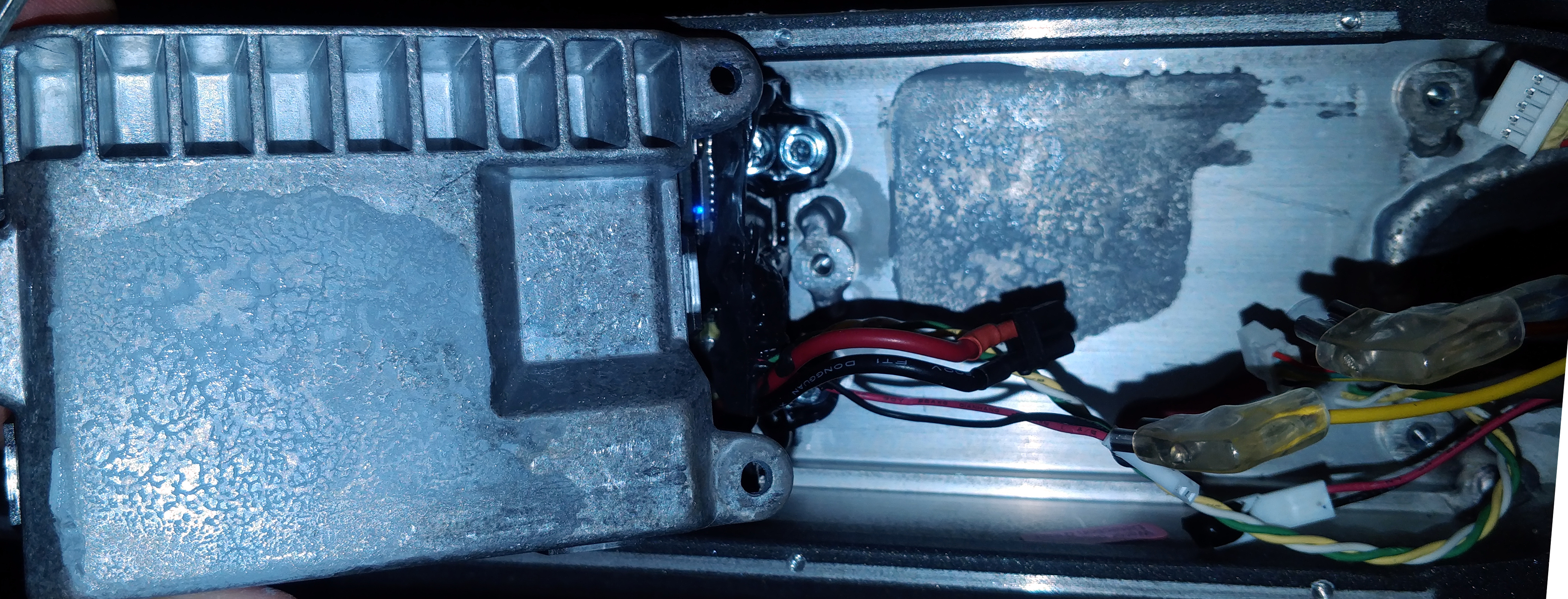
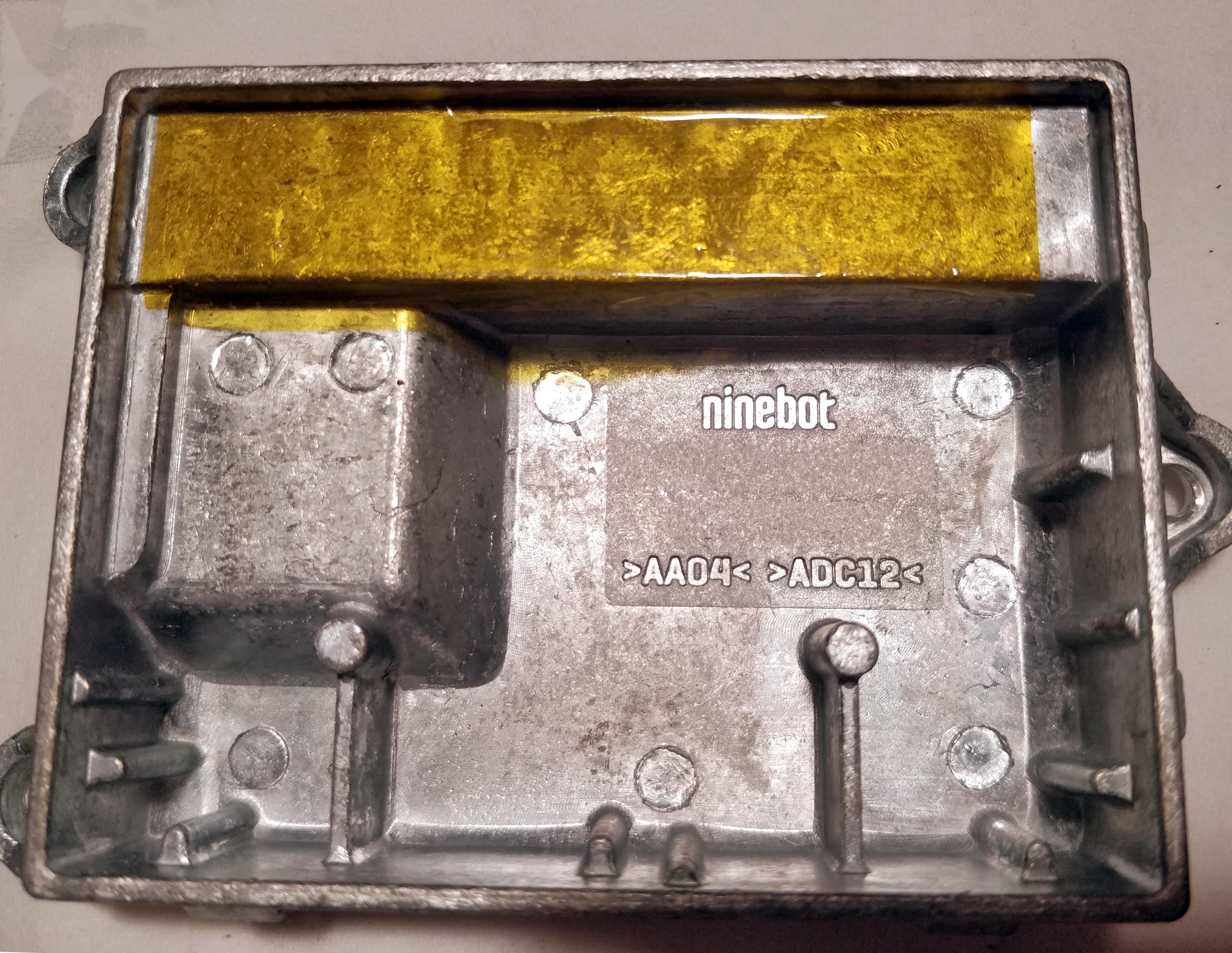
Mine had a seemingly fair bit of thermal grease under it:
[
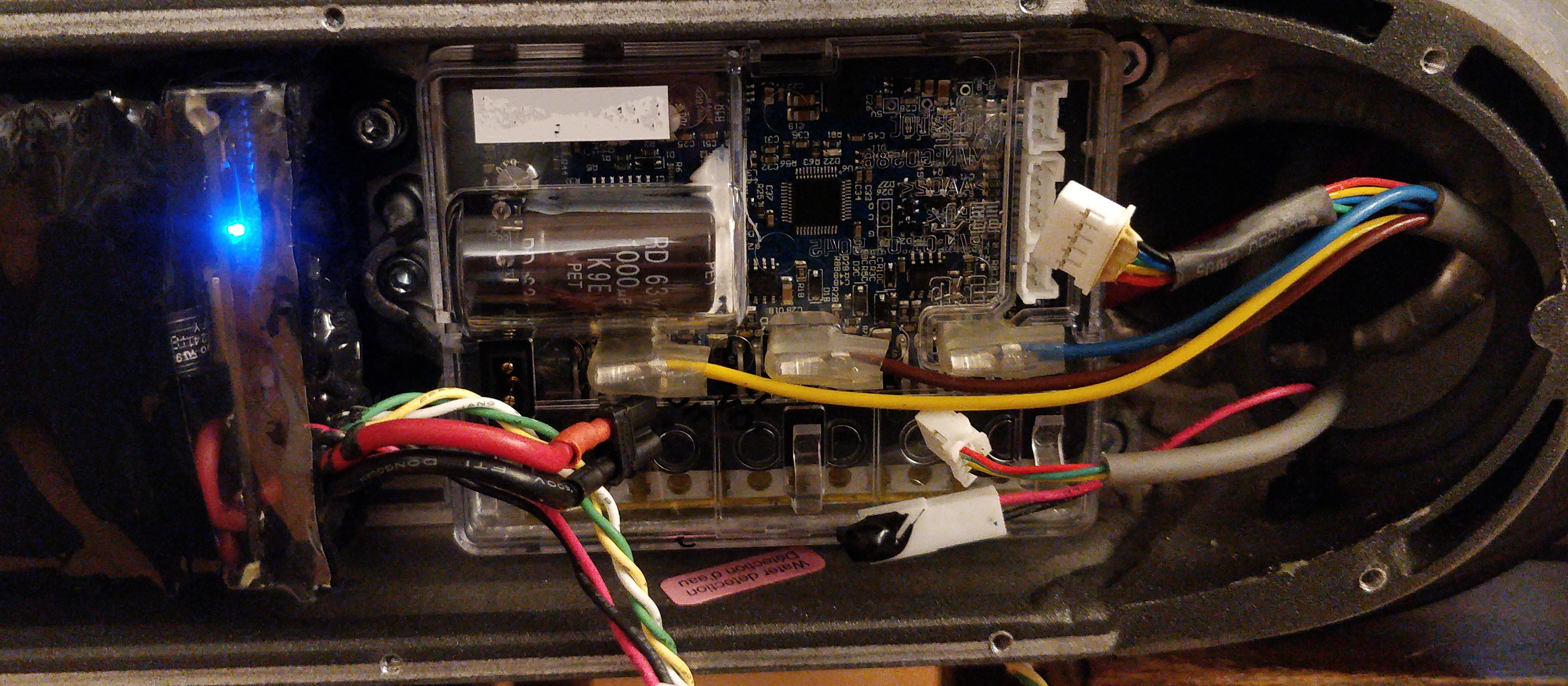
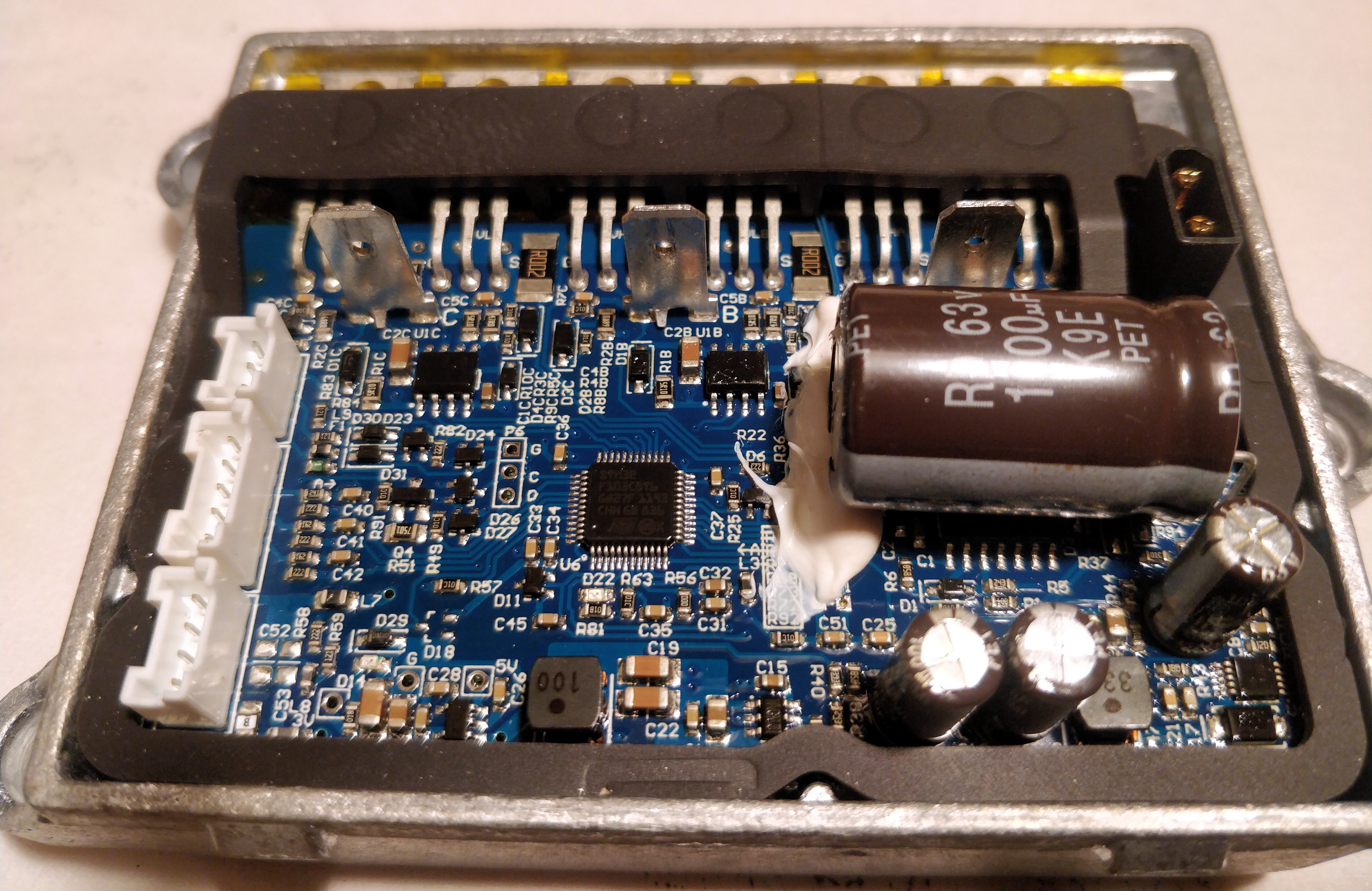
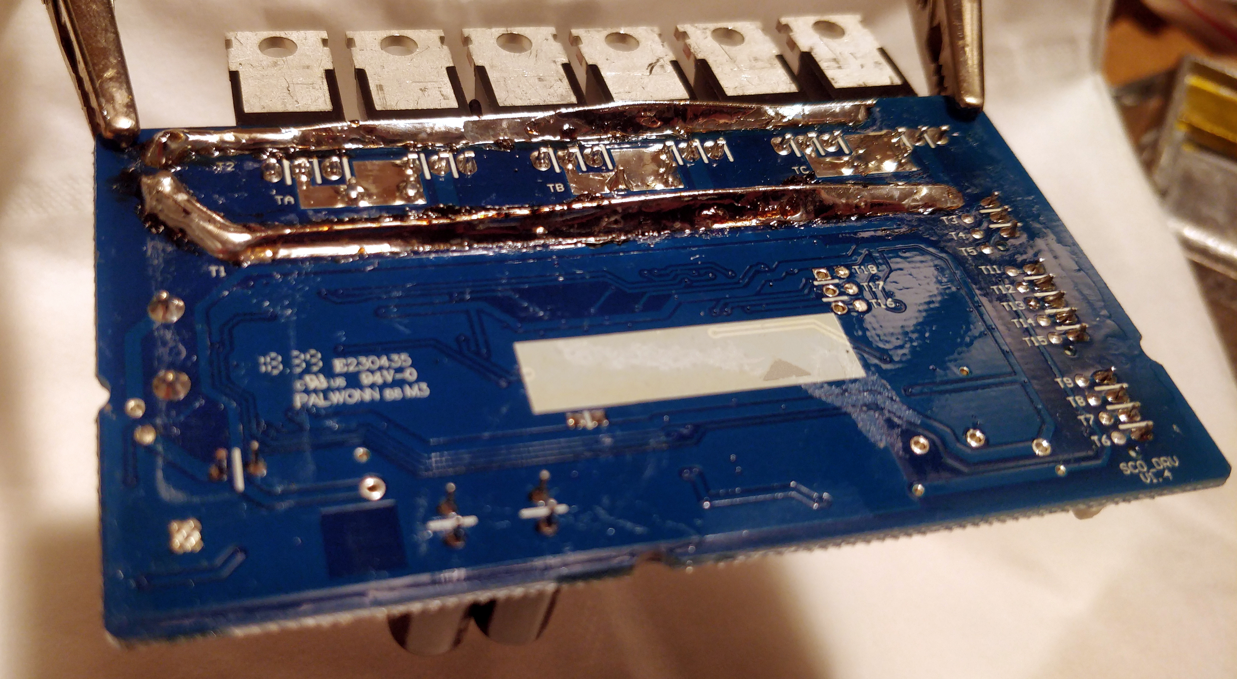
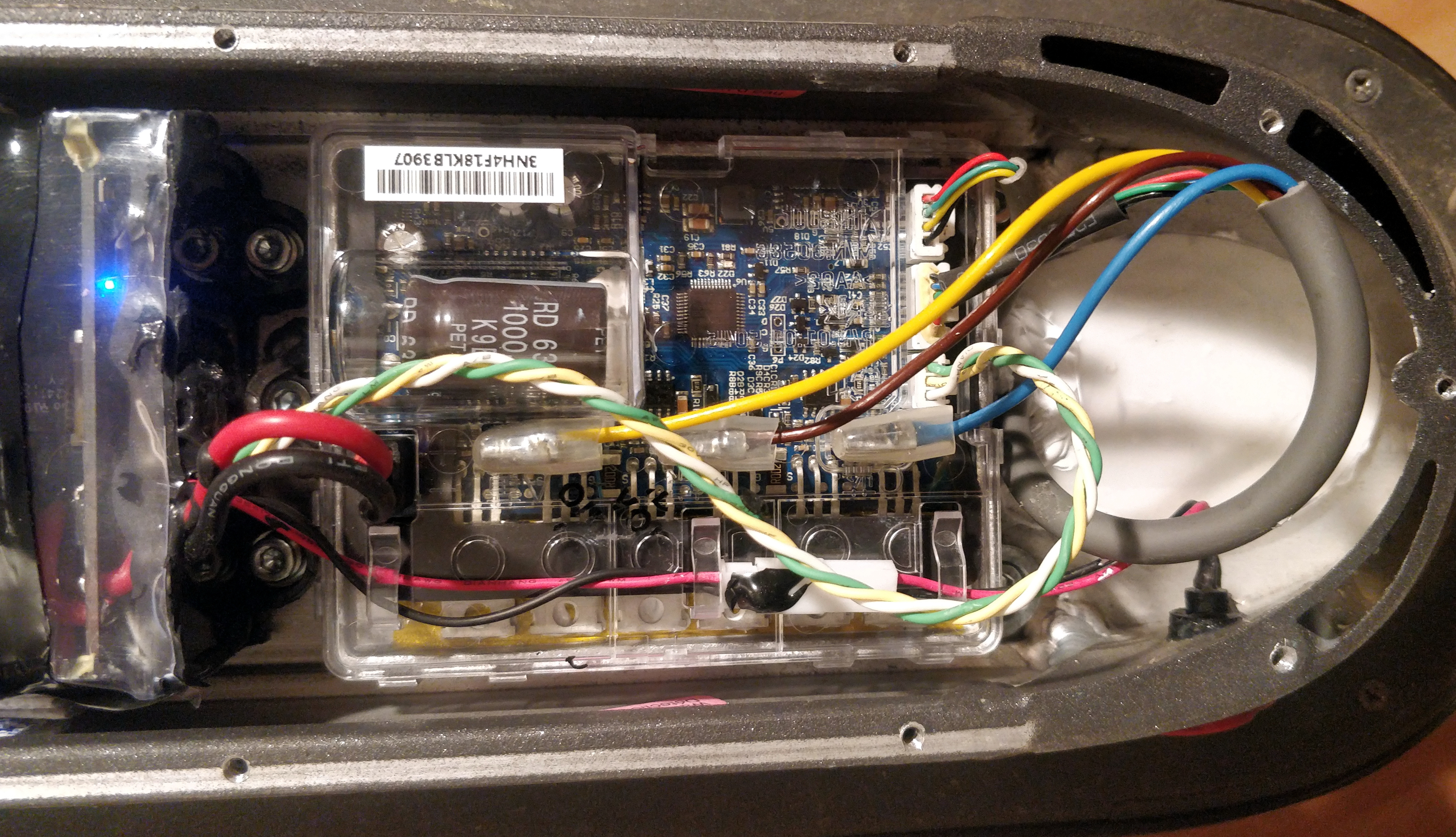
Let’s see what’s inside:
SAFETY WARNING: Don’t even try this if you are not familiar with handling or repairing electronics. For example, that huge capacitor can easily shock you. Seriously, no kidding here. (At least discharge it with an insulated screwdriver.)
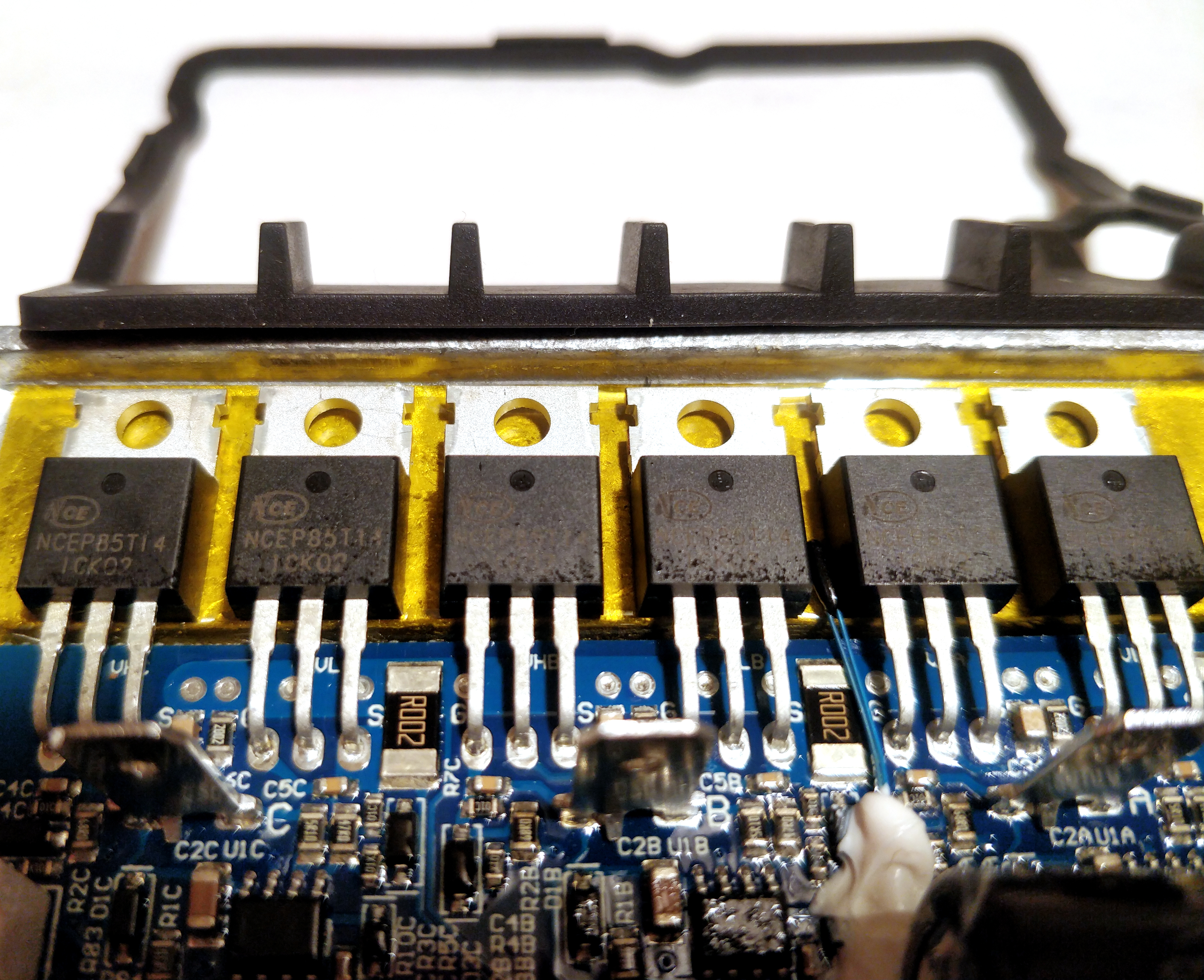
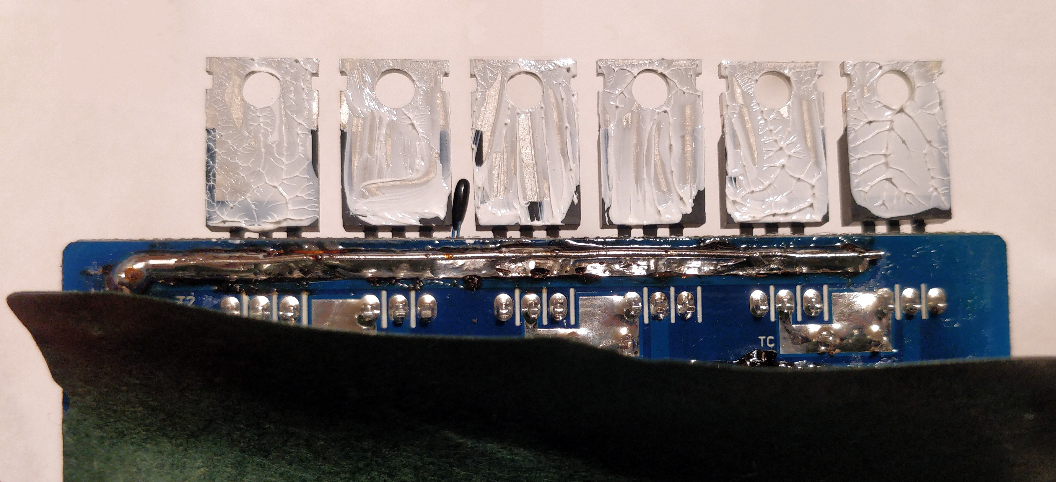
The FETs were held down by a rubber ring, also between the 4th and the 5th FET you can see the small thermal sensor too.
The yellow tape, called Kapton tape is a bit ambivalent for me. Kapton is an awesome material, very good at electrical insulation even at extreme temperatures. But as far as I understand, it’s not so good in thermal conductivity around room temperature. But there are versions/composites of it that are good in both electrical insulation and thermal conductivity also. So we don’t really know which one the factory used here.
I’ve put the aluminum frame on an electric stove (without the circuit) just for a quick ’n’ dirty test: with my fingers, I could not determine any serious thermal insulation on the yellow tape. Since it is very thin I would have been surprised to find any other result than this.
So I’ve assumed that tape is enough. I skipped my plans to rip it off and use crystal insulators instead.
One thing we should be sure about: the FETs should be electrically insulated from the case and from each other too. I’ve measured: only every second FET’s backplate was connected. So to be on the safe side, leave them ‘alone’ and don’t do anything that would connect them to anywhere.
Fixing the controller
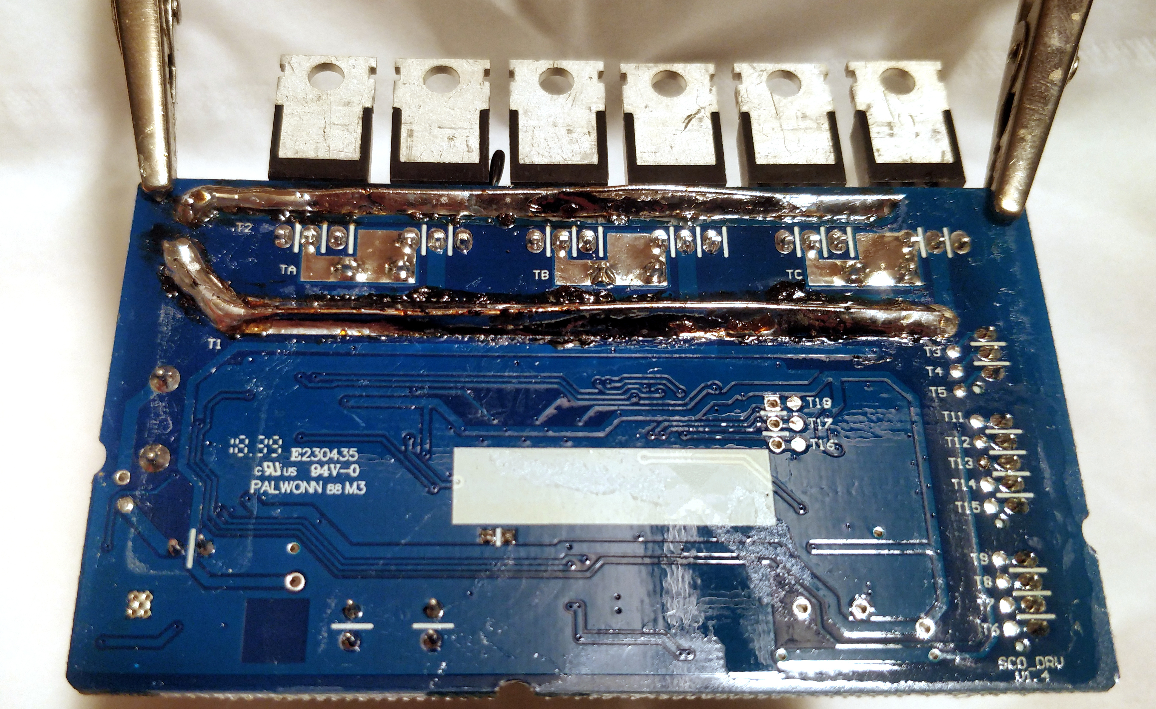
One thing I’ve done to the controller was to add thermal grease under the FETs. Although I’ve used a high-quality one and also confirmed that it is, in fact does not conduct electricity, still, I’ve used just as much as required, carefully avoiding the overflowing paste to touch the surrounding FETs.
The second thing was to add more material (namely solder & a straightened paperclip) on the main busses coming from the battery to the FETs. The reason for this is that I’ve seen too many burnt controllers on the facebook groups having these lines burned:) (Mostly PROs.)
So here we are right now:
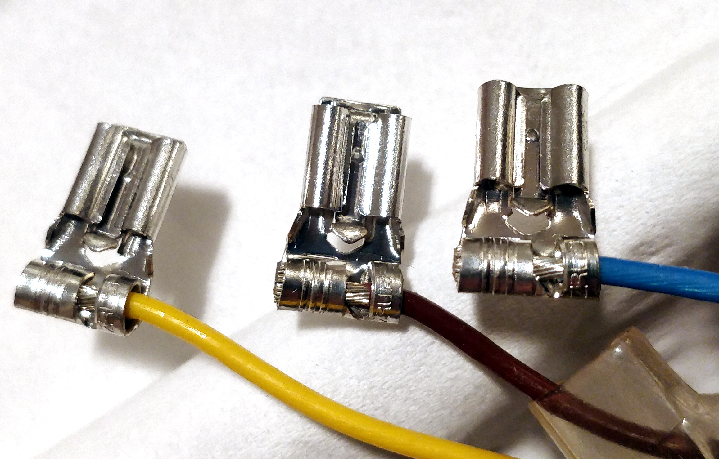
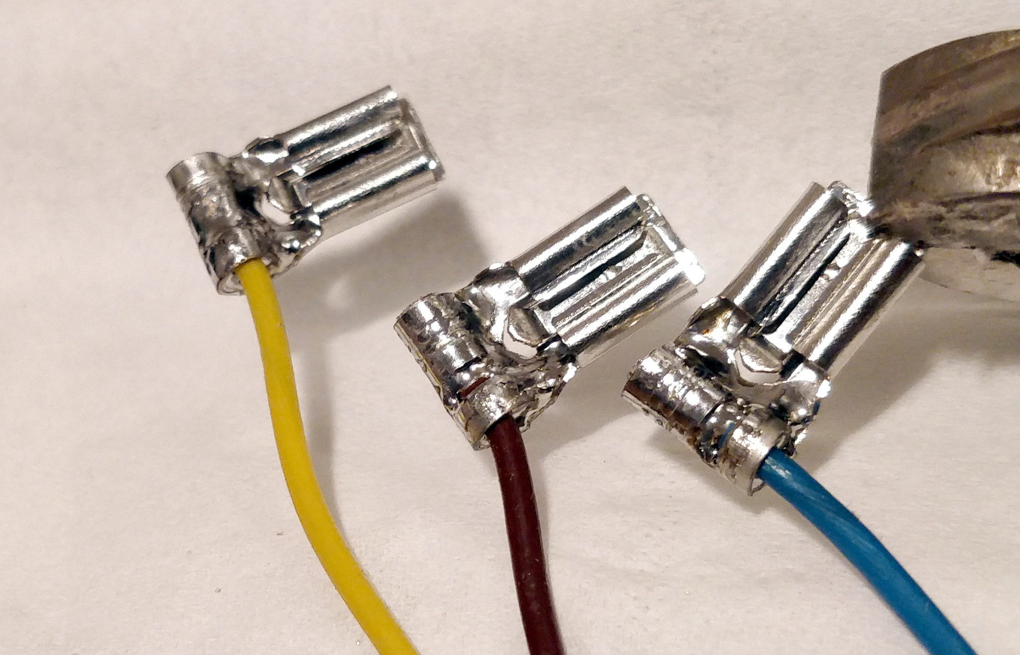
Fixing the motor’s connectors
On a few occasions (with other users), I’ve seen some burn marks on the motor connections too, so quickly added a bit of solder on them:
The extra hole!
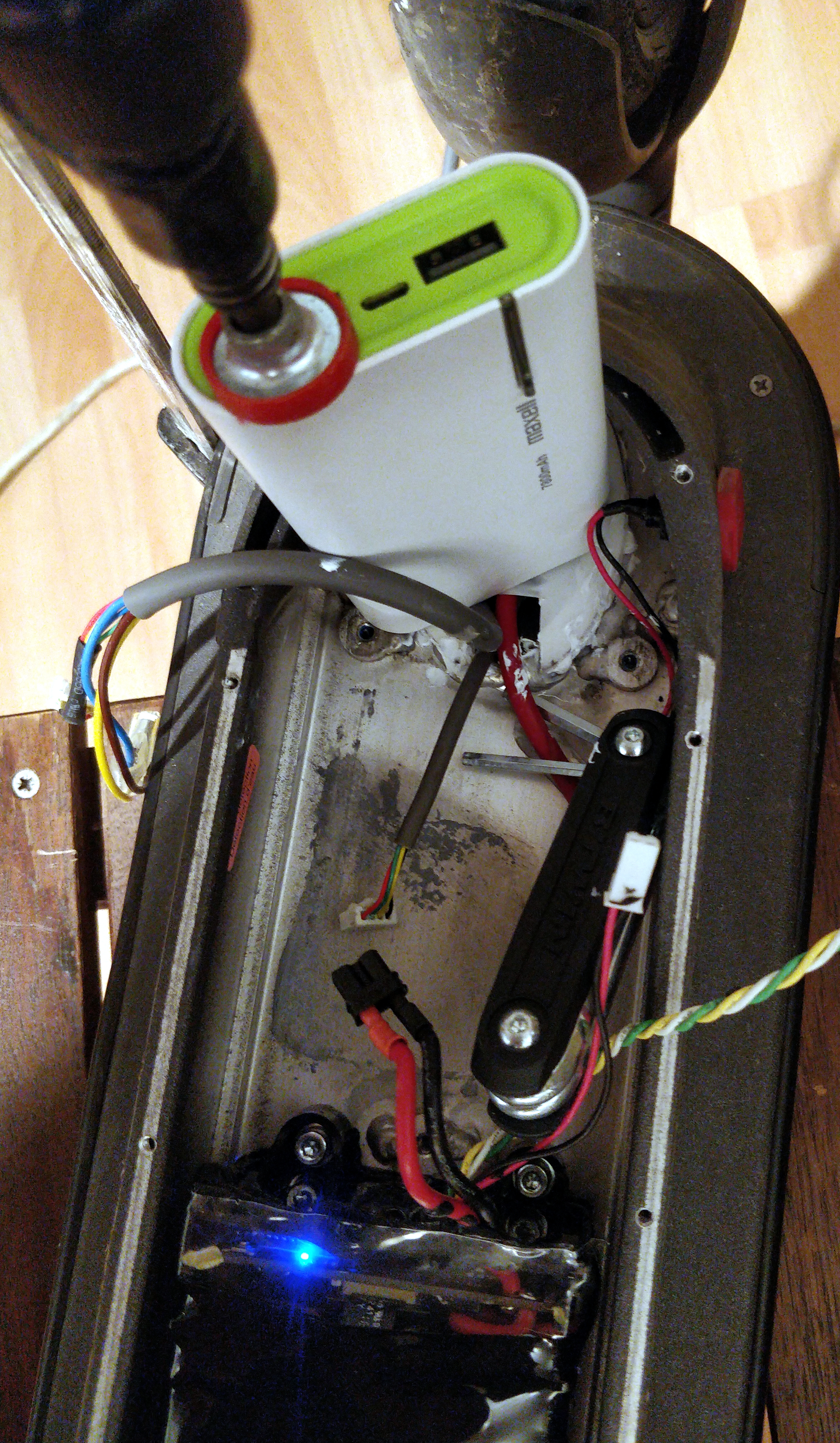
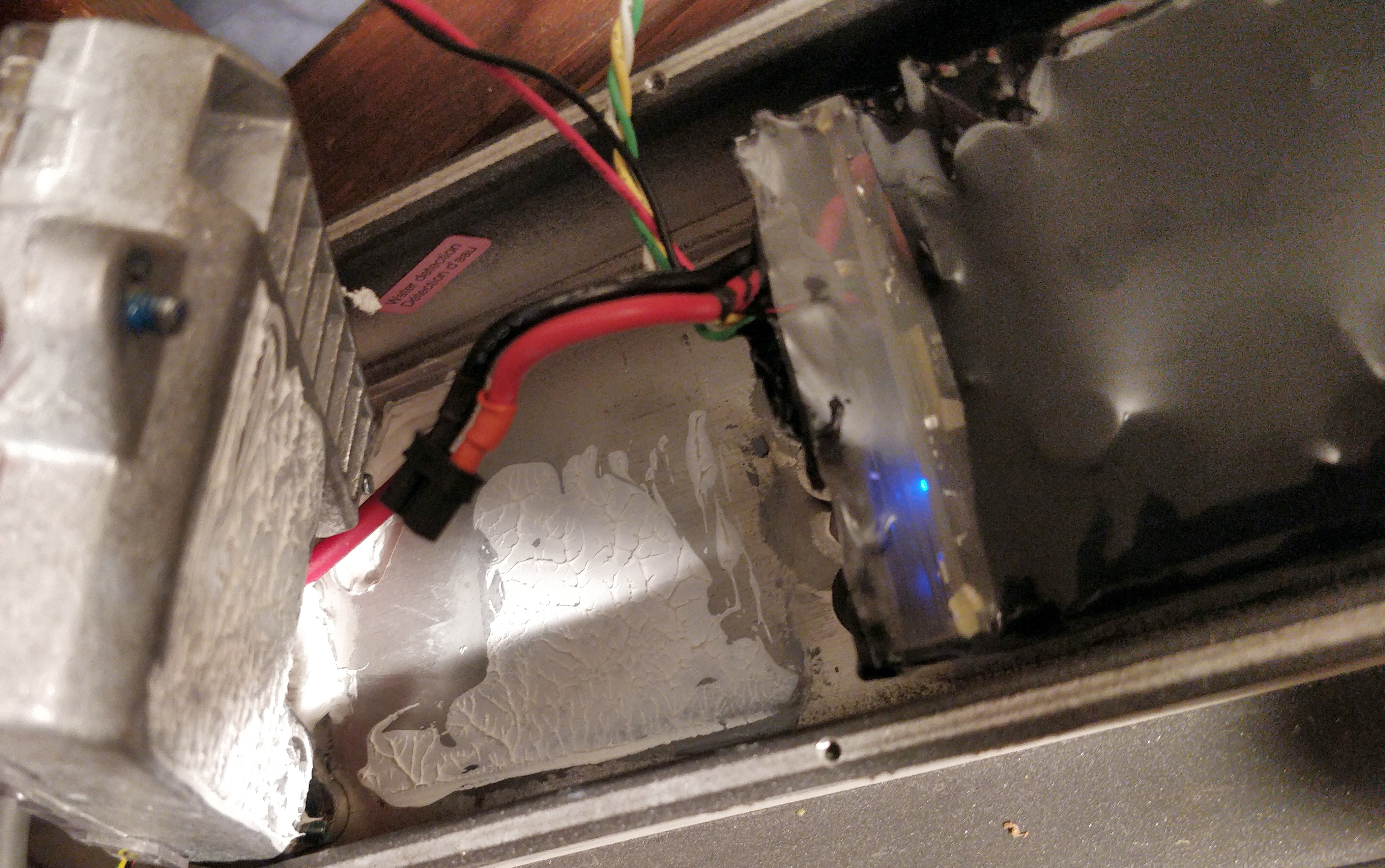
Upon fiddling with the controller, I’ve found this:
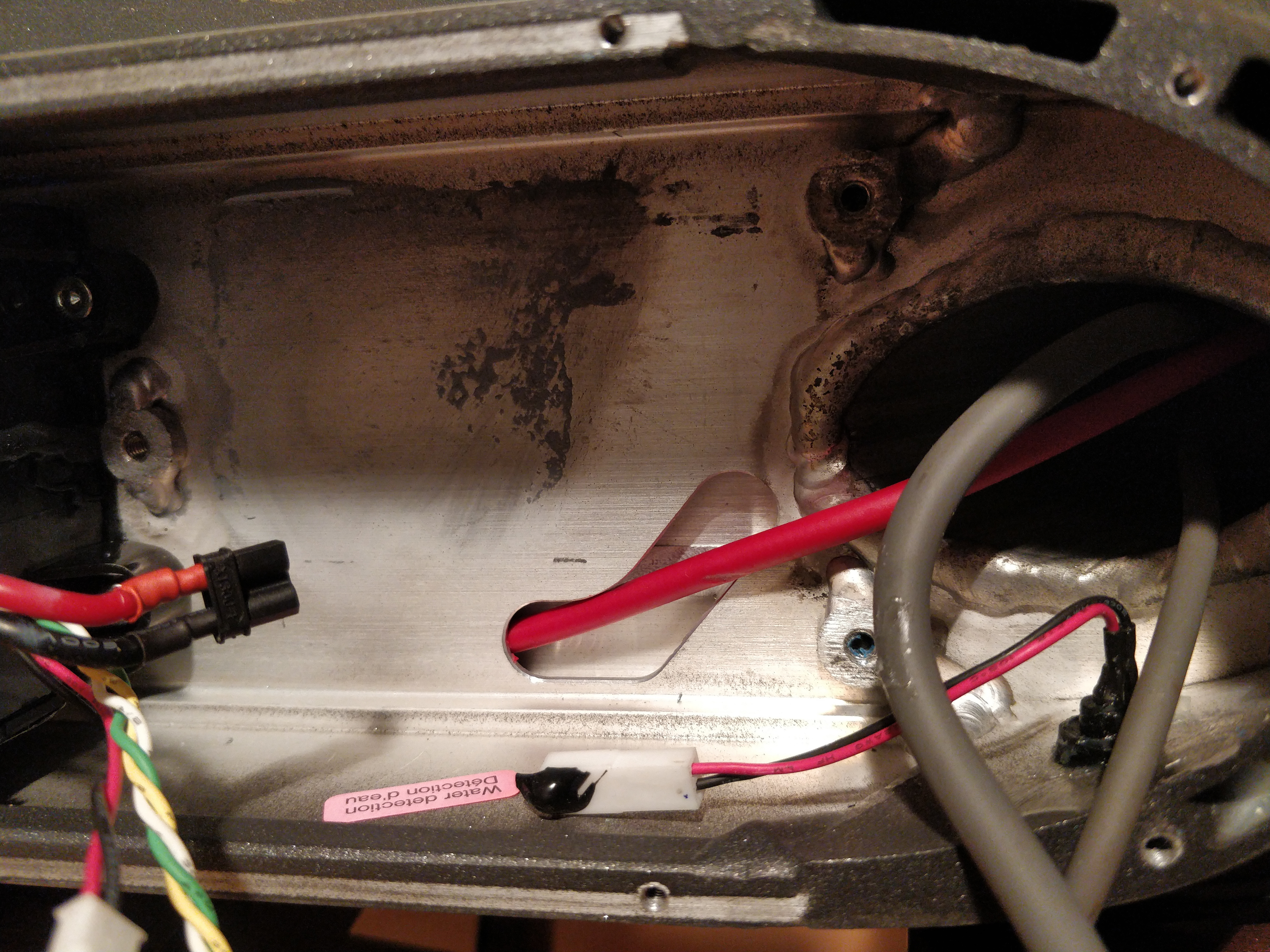
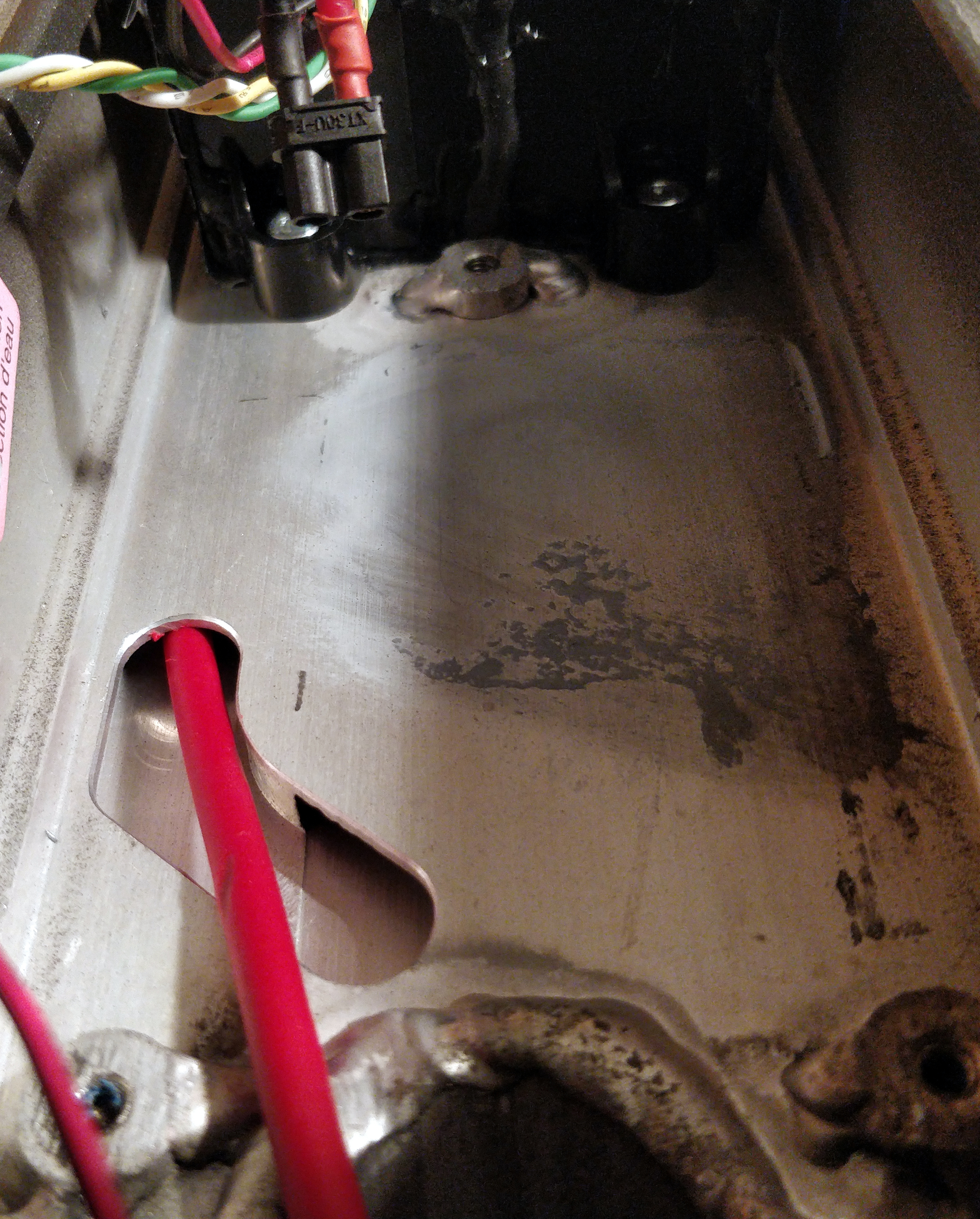
The thick red wire in the middle is the brake cable, and it just hides away in that hole. That hole’s other end is where the brake cable exits at the rear of the scooter, next to the (potentially water sprinkling) wheel. So there is an almost direct path for the water to reach the bottom of the controller, as this hole is right under it. That’s not nice.
This is not nice either, but on the other hand, very practical :)
Increasing water resistance even more
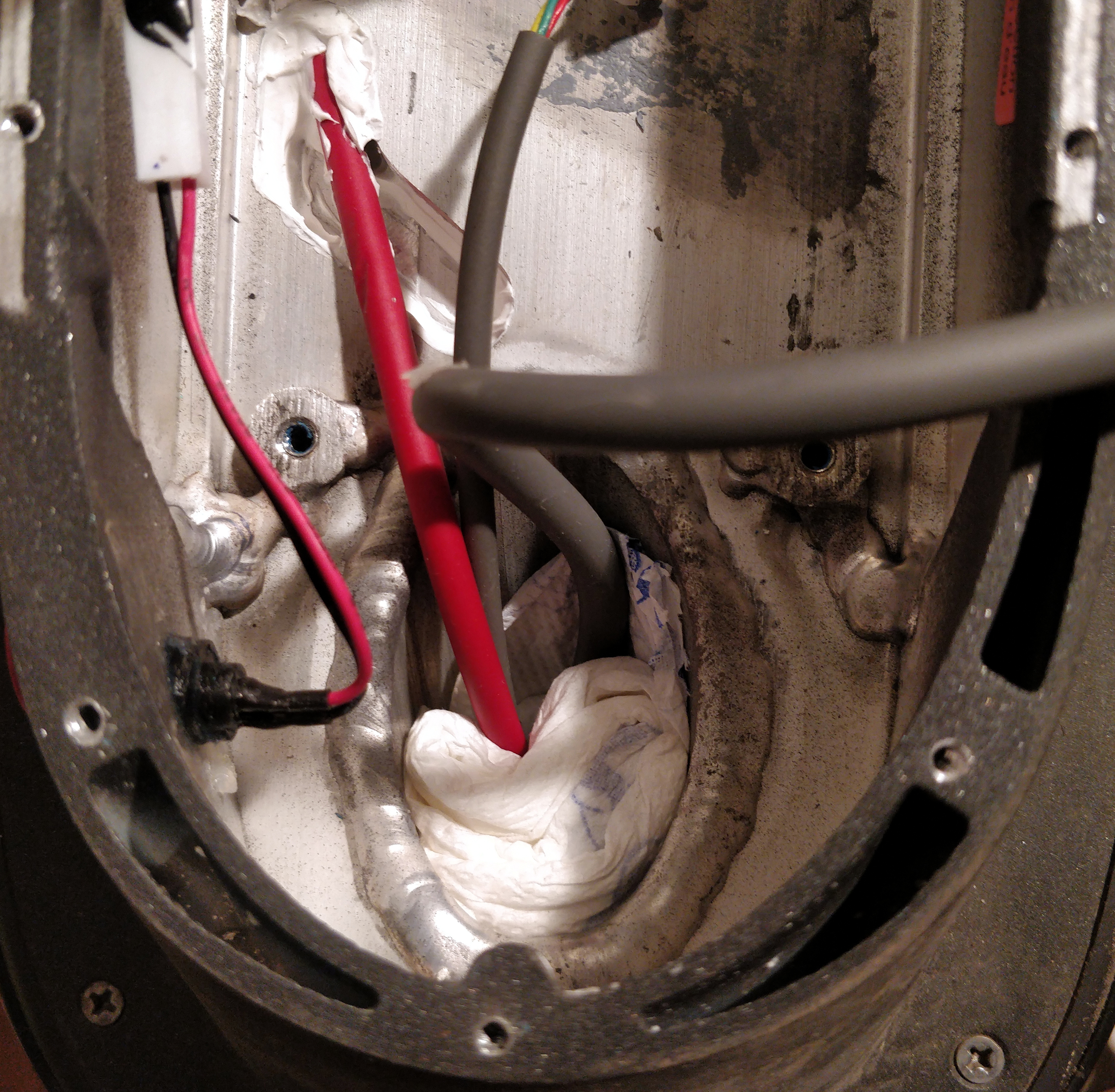
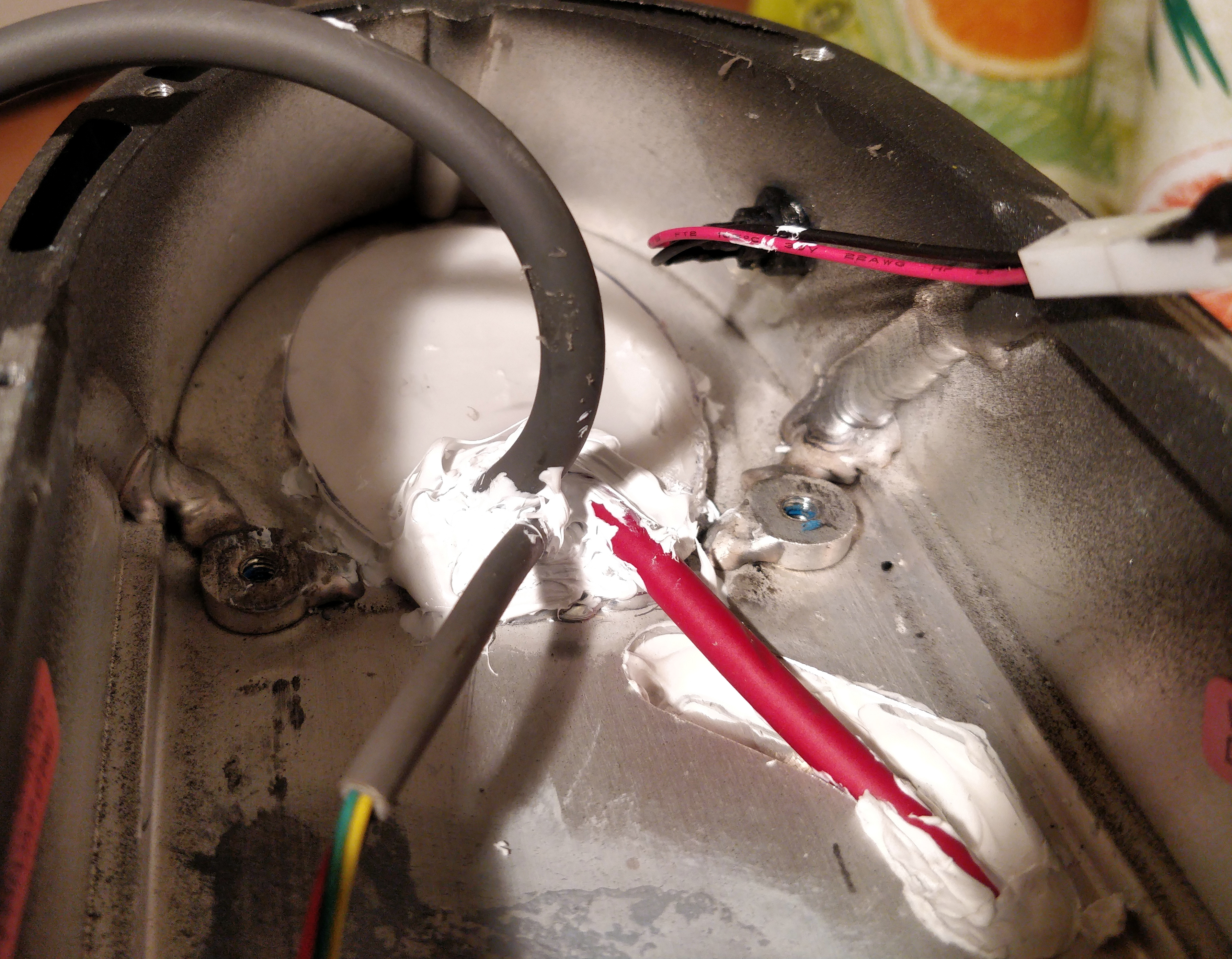
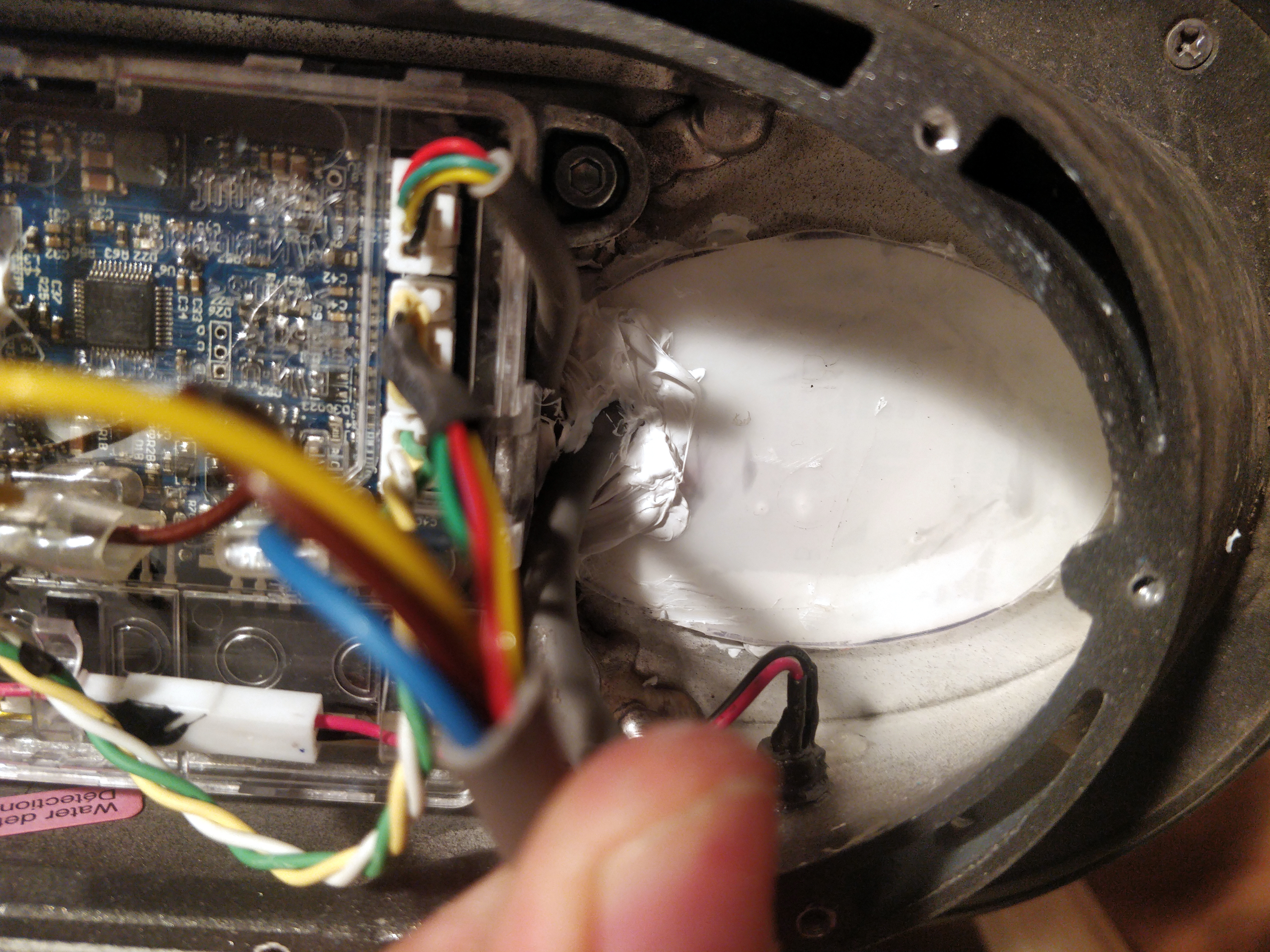
When I’ve done this, I started to think about how could I plug that big hole too:
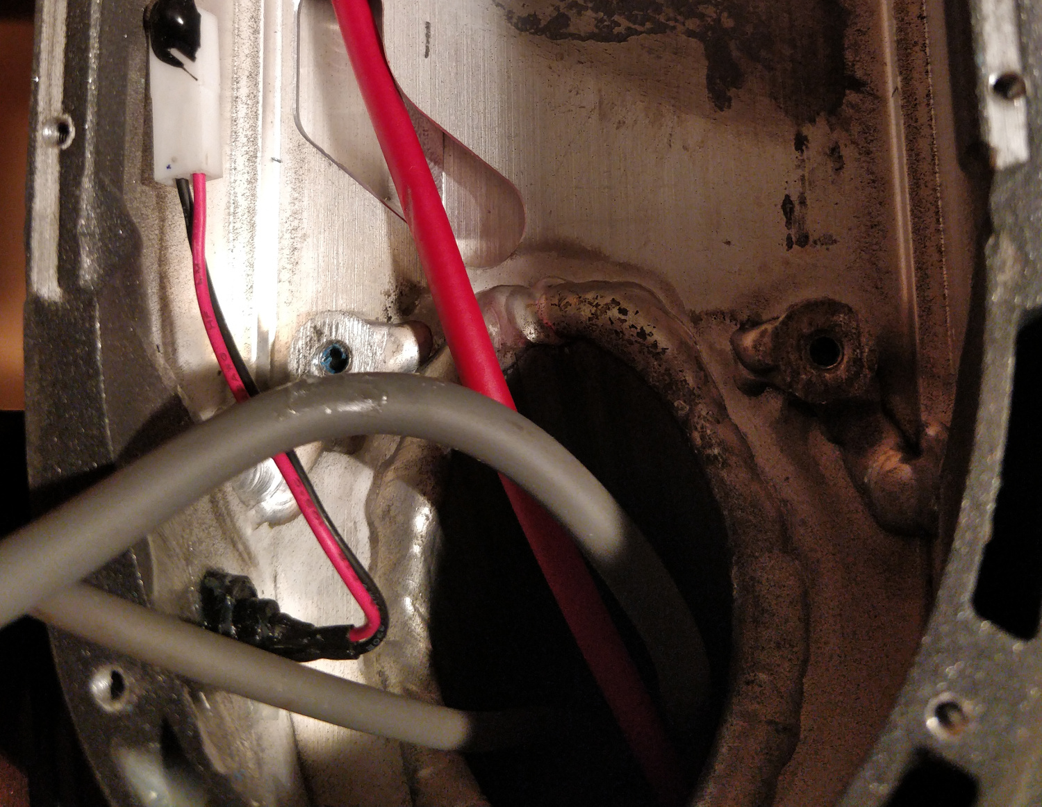
This big hole is the inside of the tube that holds the steering shaft & the wheel. The three wires are coming from the brake (red), the top controls (thin gray) and the motor (thick gray).
On this hole, there is a chance for water to sweep in, as that rubber where the cables exit the tube isn’t fully watertight.
If I had filled it up with for example polyurethane foam that would have solved the problem once and for all, and it would be easy too. But I would never be able to repair any cables anymore.
I’ve decided to design a cover instead, that will be held by construction adhesive. This way I can seal that hole in a way that can be undone with a little mess only. And that is fine, I don’t think that I will need to undo that too often.
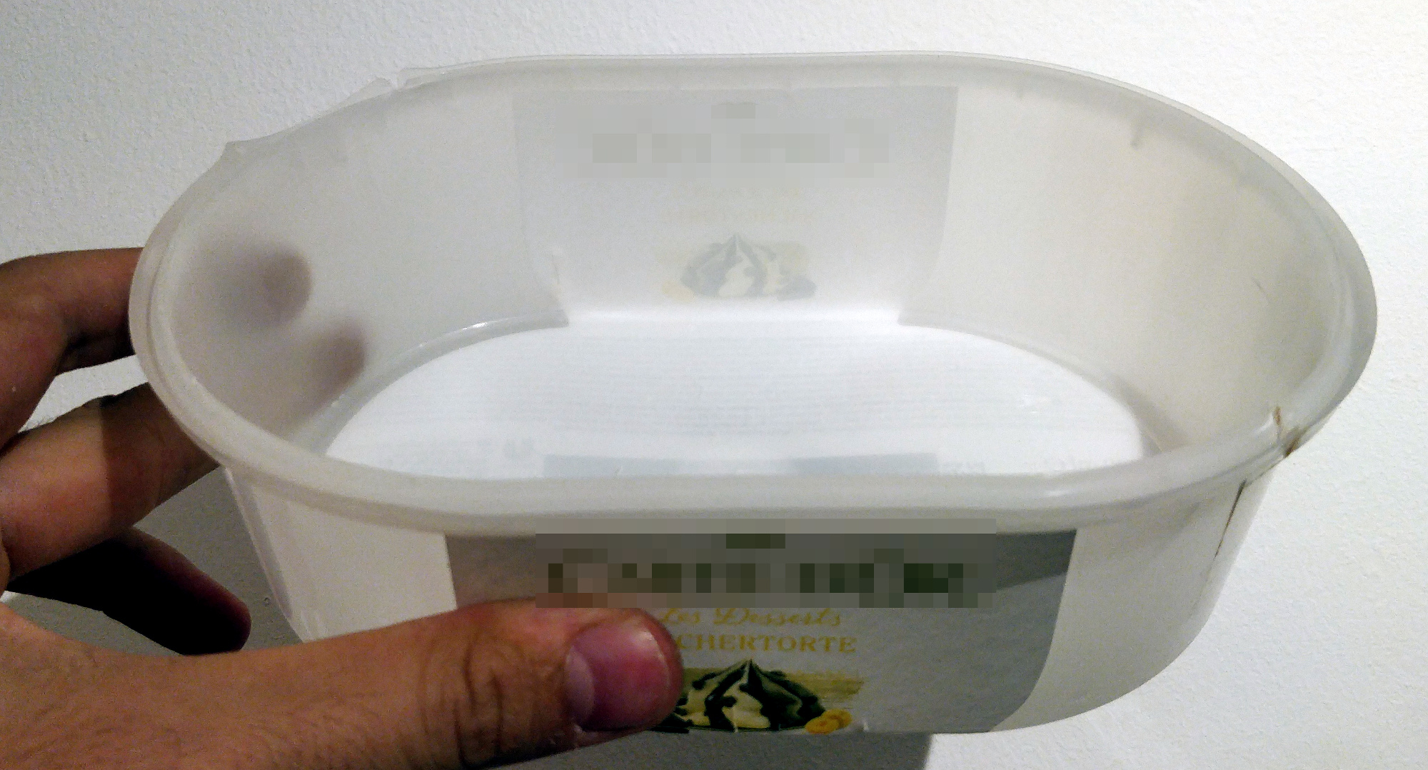
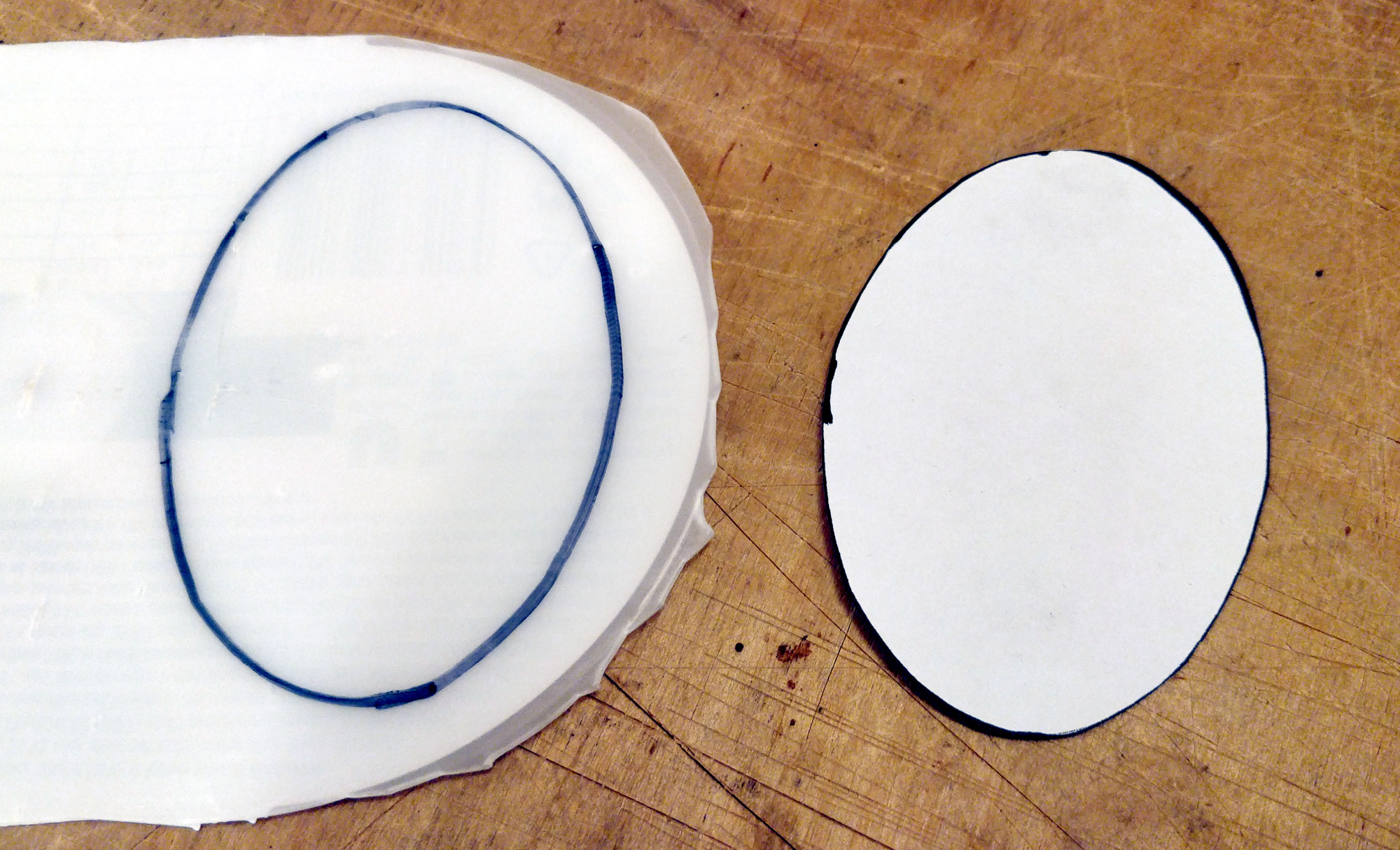
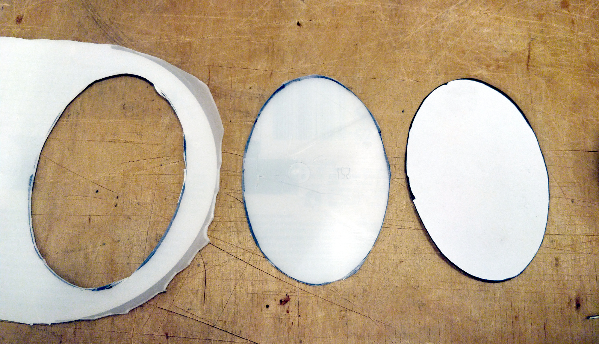
First I’ve created a template, printed it and cut it out from the bottom of an old ice cream box. If for some reason you’d need that, here is the final version:
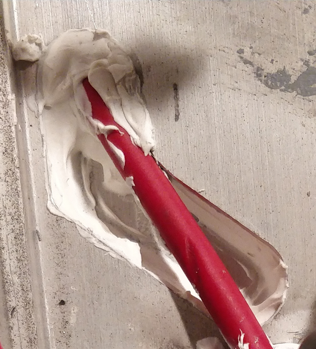
Then I went on, added a bit of paper towel into the hole, just for extra safety, and glued the cover (without the cables) first.
That poor battery bank was at the wrong place at the wrong time :) The brake wire also needed some support while the glue was curing.
This is how the finished result looked like:
This way, if I ever need to replace or pull the cables… well it’s not fun, but possible. I just need to remove that cover and that small bit of glue from the wires.
The bottom plate
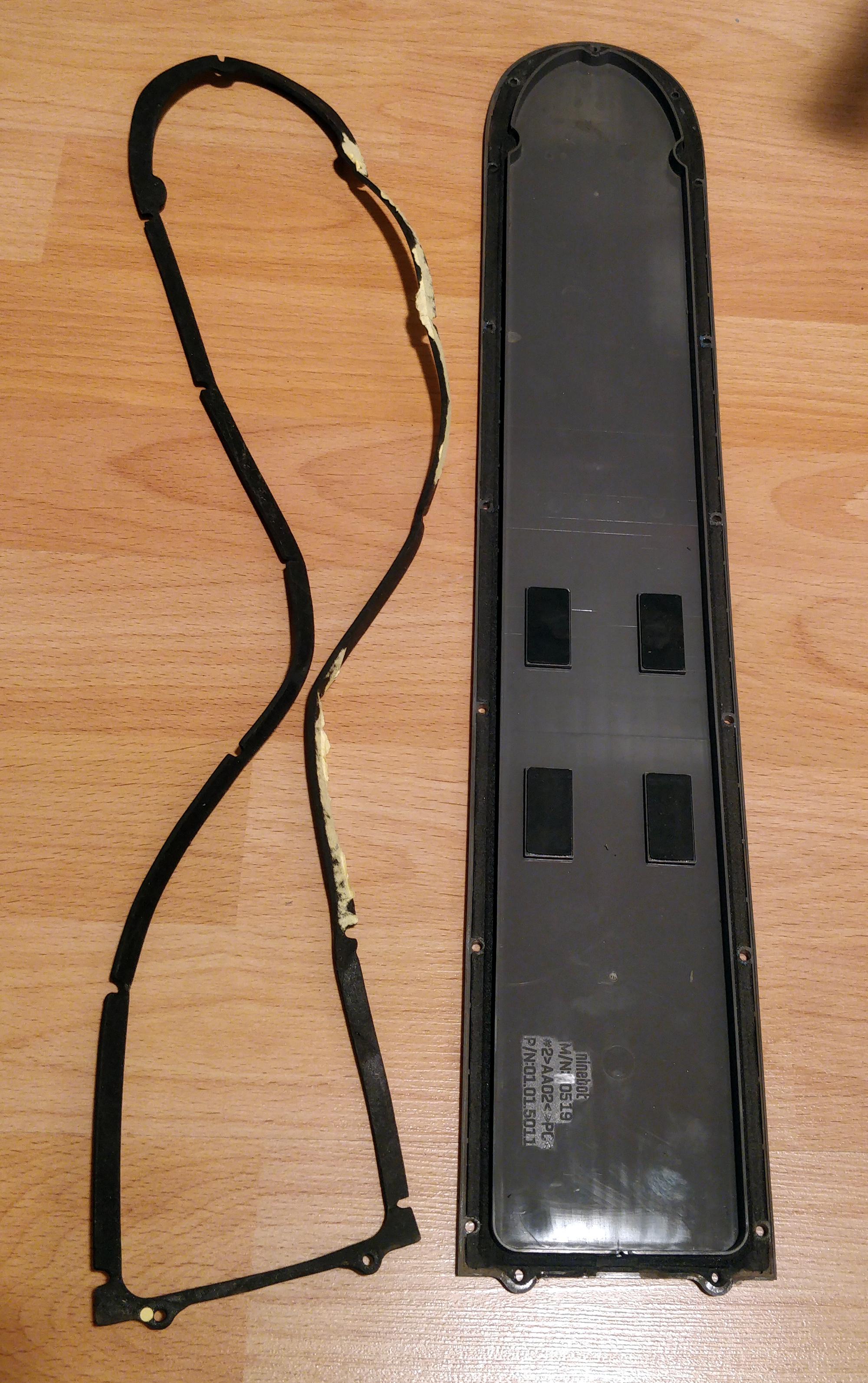
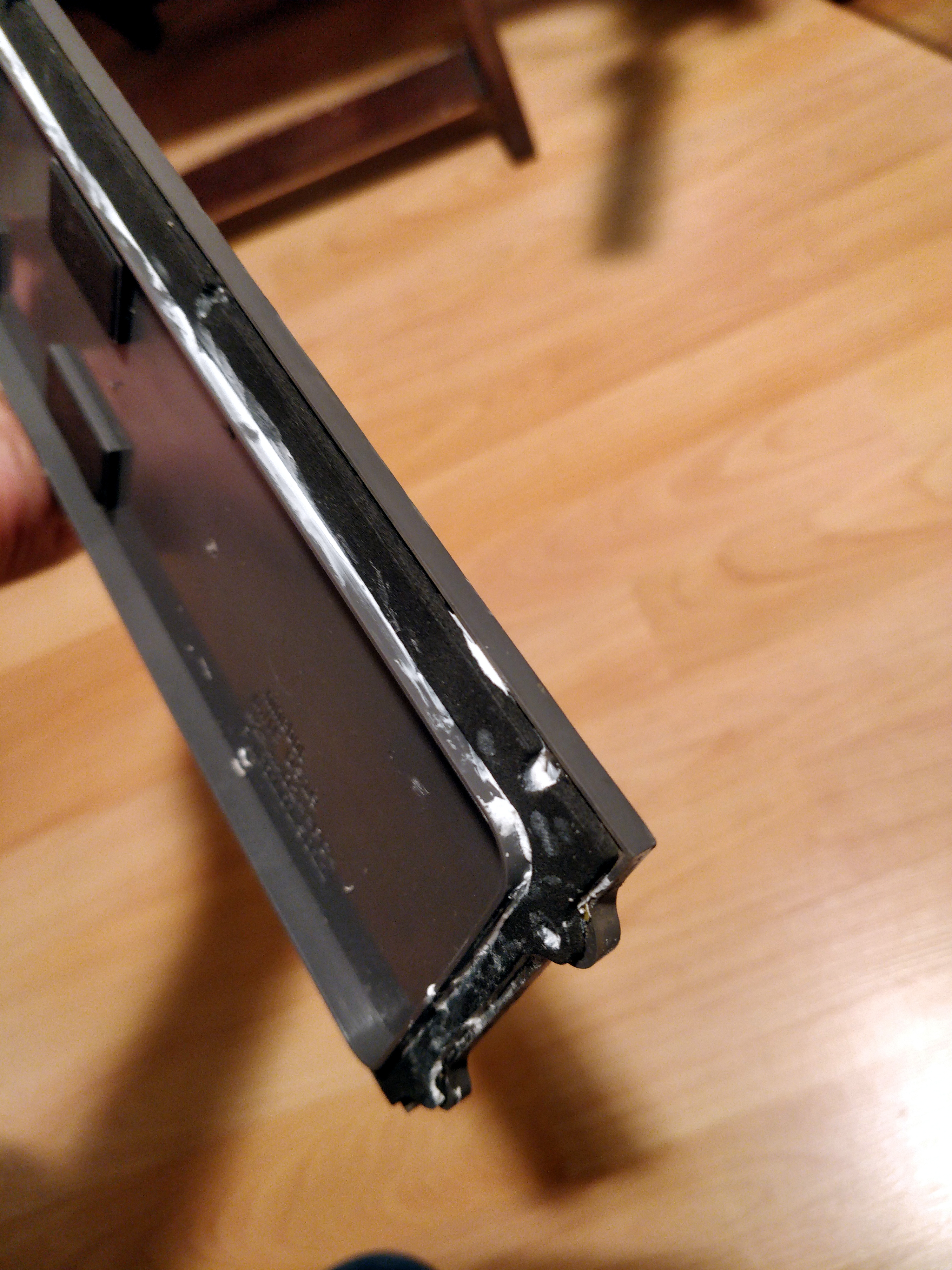
I’ve bought an extra sealing ring for the bottom plate. Its quality is pretty crappy, the glue doesn’t stick, the yellow masking paper wouldn’t peel off at some places… Horrible.
Anyways, I decided to glue it onto the original.
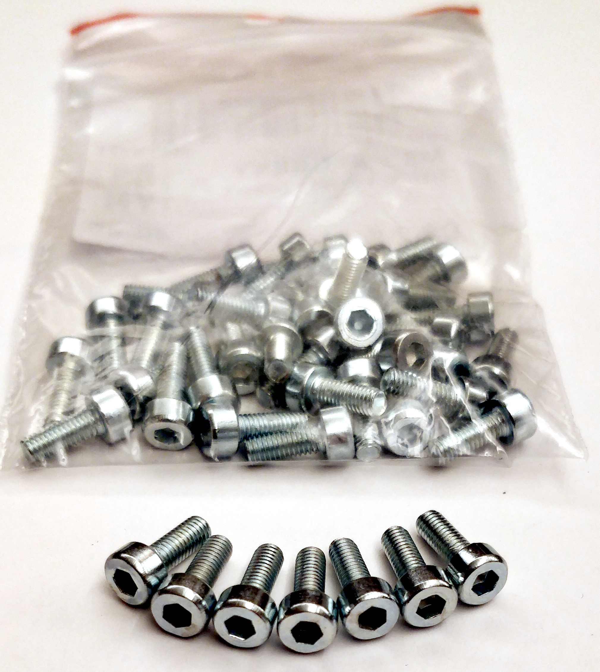
And it’s a good time to install the new screws instead of the original ones too. The problem is that the original screws (not just here) are either weak, or their heads are not exactly round number sized (2.5 instead of 2 mm, etc.) or both. So if you mess with them often, they will wear out quickly, and you will be unable to unscrew them, which is quite sad.
The end
After adding some thermal grease to the bottom of the controller, and putting back everything: I’m finished.
Hopefully, if the bottom cover holds up well, there is no way for water to enter into this section of the scooter. The motor and the control panel is still vulnerable on the other hand, so I still wouldn’t use it in a swimming pool :)
I hope that you found this interesting! Let me know in the comment section what you think!